
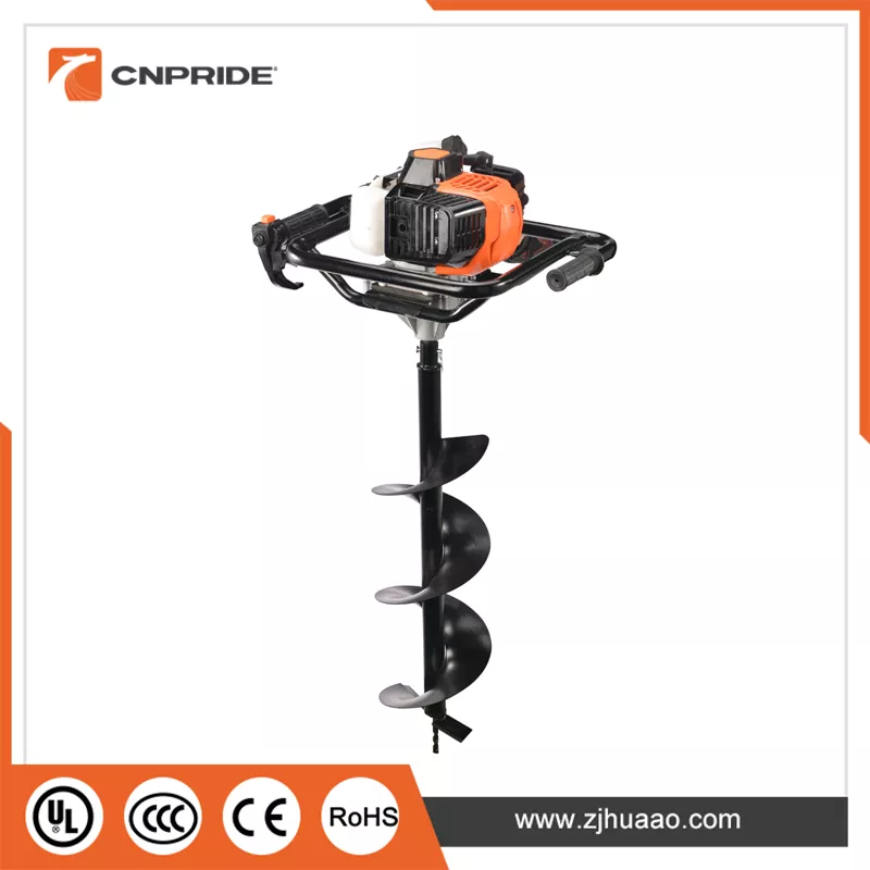
At the heart of most portable Gasoline Earth Augers is an air-cooled, two-stroke, single-cylinder gasoline engine. This engine type is chosen for its exceptional power-to-weight ratio and mechanical simplicity, both of which are critical for handheld or light-duty equipment operating in remote outdoor environments.
Displacement and Power Output: Engine displacement typically ranges from 52cc in entry-level models to 80cc or higher in heavy-duty variants. This displacement translates to power outputs of approximately 1.8 kW (2.4 HP) to 3 kW (4 HP). The power curve is governed by engine speed, with most units operating at no-load speeds of 2,100 to 8,500 rpm, delivering torque through a reduction gearbox to the output spindle.
Fuel and Lubrication System: Unlike four-stroke engines, the two-stroke cycle requires a pre-mixed fuel-oil blend. The industry-standard mixing ratio is typically 25:1 or 40:1 (gasoline to two-stroke oil), depending on the manufacturer's specifications and oil grade. To improve cold-start reliability, most units incorporate a primer bulb (fuel pump) upstream of the carburetor, allowing the operator to manually draw fuel into the carburetor bowl before the first pull. The fuel tank capacity is generally 1.0 to 1.2 liters, providing sufficient runtime for extended field operations.
Ignition and Starting System: The ignition system employs a capacitor discharge ignition (CDI) module, which delivers a stable high-voltage spark without external power. Starting is achieved via a recoil (pull-cord) starter, which engages the engine flywheel when pulled. The engineering advantage of this system lies in its complete independence from electrical grids, ensuring reliable operation in remote wilderness, mountainous terrain, and other off-grid work sites.
The transfer of mechanical energy from the engine to the ground involves several critical components designed to manage torque, reduce speed, and isolate vibration.
Centrifugal Clutch and Power Engagement Logic: A centrifugal clutch is installed between the engine crankshaft output and the gearbox input. Its operating principle is governed by centrifugal force: at idle speeds, the clutch shoes remain retracted under spring tension, transmitting no power. As the throttle opens and engine speed rises to the engagement threshold (typically 2,500-3,000 rpm), the shoes expand outward due to centrifugal force, engaging the clutch drum and smoothly transmitting power to the gearbox. The engineering significance of this design is twofold: the auger bit remains completely stationary at idle, enhancing operator safety and preventing unnecessary wear and fuel consumption during positioning.
The operational capability of the Gasoline Earth Auger depends not only on power and transmission but also on the terminal cutting element—the auger bit. Its geometry is far more sophisticated than a simple helical plate; it is a compound structure optimized through fluid dynamics and soil mechanics.
Pilot Point and Cutting Edge – The Penetration Mechanism: The lowermost section of the bit features the pilot point, typically a conical or cross-shaped structure often tipped with cemented carbide inserts. Its function is to provide centering stability during the initial stage of drilling, preventing the bit from skidding or deflecting upon ground contact. Immediately above the pilot point are the main cutting edges, whose geometric angles—rake angle, clearance angle, and cutting edge inclination—directly influence the specific energy consumption required for soil penetration. For heavy-load applications involving gravel or frozen soil, premium bits incorporate carbide-tipped inserts on the main cutting edges, dramatically improving wear resistance and impact toughness.
Double Flight and Variable-Pitch Designs: To handle complex geological conditions where soil layers alternate unpredictably, some professional-grade bits employ double-flight configurations—two parallel helical flights that simultaneously improve chip evacuation efficiency and enhance down-hole guidance stability. Additionally, variable-pitch designs (shorter pitch at the bottom, longer pitch at the top) provide greater cutting force during initial penetration while accelerating chip discharge in the upper section, preventing soil accumulation against the borehole wall.
Operation of the Gasoline Earth Auger is not as simple as "opening the throttle and drilling." The depth of its safety protection system directly determines equipment lifespan and operator safety.
Throttle Control and Engine Speed Regulation: The handle assembly incorporates a trigger-type throttle control, connected via cable to the carburetor throttle plate. The operator achieves continuous speed modulation through finger pressure. Some models feature a throttle lock button adjacent to the trigger, allowing fixed throttle position during continuous operation to reduce finger fatigue from sustained pressure.
Maintenance of the Gasoline Earth Auger is fundamentally the care of a two-stroke engine and mechanical transmission system. Its core principles can be summarized in three key practices:
Fuel Freshness: Pre-mixed two-stroke fuel begins to degrade after 30 days of storage, as light fractions evaporate and oxidative gums form, readily clogging carburetor jets and passages. Engineering best practice recommends using ethanol-stabilized specialty two-stroke fuel, or draining the tank and running the engine dry until the carburetor is depleted after each work session.
Air Filter Cleaning: Drilling operations generate substantial dust. Foam or paper air filter elements require daily cleaning. A clogged air filter causes rich mixture conditions, incomplete combustion, accelerated carbon buildup, and ultimately cylinder scoring or seizure.
Gearbox Lubrication: The reduction gearbox is filled with specialized gear grease (typically NLGI Grade 2 lithium-based grease). Regular inspection and replenishment are essential to prevent premature gear failure from dry running.
The Gasoline Earth Auger is far more than a simple "gasoline engine with a screw rod"; it is a sophisticated ground-drilling system that integrates combustion dynamics, mechanical transmission engineering, soil cutting mechanics, and ergonomics. The elegance of its design is evident in the centrifugal clutch's smooth power engagement, the gearbox's precise torque amplification, the shear pin's role as the final line of defense for machine safety, and the helical flight's precise control over soil chip flow. Only by understanding these deep technical principles can one truly master this equipment and apply it with scientific maintenance and efficient operation.


